Low Price CNC Machined Parts Never have smooth round edges
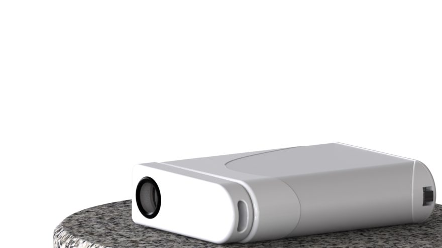
The photo below is a classic example of CNC Public Enemy #1. Smooth round edges or external radii can cause a design to shoot up in price by as much as 5X in worst case scenarios.
Why? Because the CNC machine has to trace edges and paths multiple times, and that creates an enormous amount of time you end up paying for unnecessarily.
I know, a smooth round edge is an oxymoron, but how else to describe it? Where there should be an edge, a radial surface exists. When we receive RFQs for designs with external radii on all the edges, we’re quickly disappointed. It will be next to impossible to offer a low price for a simple part that should be easy to make.
Product design is an art intertwined with engineering and manufacturing knowledge. Adding edge radii purely for cosmetic reasons is a mistake; that fillet feature in your CAD software should be used for functional purposes only.
Designing for the Production Process Upfront is Dangerous
When a part is destined for Plastic Injection Molding, Die-Cast, and Zinc-Cast, we can fall into an expensive edge radii design trap.
DFM Axiom 3: DFM (Design For Manufacturability) is dependent upon which phase of the project you are in. The statistical probability of your initial design hitting production is very, very low. If the end process is plastic injection molding, spending the time and effort to design for it upfront is a waste when producing conceptual and functional prototypes and the features like edge radii, drafts and other’s drive the cost of the prototype up 2-3x unnecessarily.
Here’s a helpful hint: Use configurations in your CAD package to assist. In Solidworks, it’s easy to create multiple configurations for each process. One configuration is for CNC and employs chamfers and edges. Another configuration is used for the plastic injection molding or 3d printing, employs corner radii everywhere, drafts, thinner walls, and snap fits. Another configuration optimized for production is mandatory; configurations are such a blessing, try it.
What are the General Design Rules for Adding Radii to Edges?
If handling and safety is the concern, consider chamfers and ask yourself, “Where am I in the development process? Are we making 5 prototypes and it’s in the noise? or Are these prototypes for investors and they have to be the best ever? or Are these 200 pre-production parts and I need the lowest price I can find?”
Answers to these questions are the guide to creating edge radii for cosmetic reasons or not. But really one should do everything they can not to include them because it adds so much cost and time.
- The best alternative is to leave a deburred edge.
- The second-best alternative is to make a chamfer.
- And last but not least, if you decide to sin, and add a radius to your edges, at least make them all the same size and on a flat plane; no 3D tracing of edges.
Chamfers and 3D Tracing
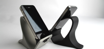
We will use common radii or chamfer tools to trace the edge. However, if it is not on a single plane, then costs rise logarithmically as we will need to 3D profile it. Look at the part below. Though it looks great on the screen, it is a nightmare and 5X more expensive to machine; please don’t design parts that look like Star Wars Tie-Fighters.
Example of Costs vs. Corner radii
This part here was originally submitted with external corner radii to break the sharp edges. In quantities of 100, $375 each, $235 with chamfers, and with edges, an appealing $170 ea. That’s $17,000 in savings you could show your boss.
- Ignoring the spline, this part is very cheap and easy to make with neither corner radii or chamfers. The first two ops are turned on a CNC lathe very quickly for the front/back profiles, bores, and spline; easy breezy. Then the third op cuts the profile and adds the countersinks. Done. It’s a $170 part at quantities of 100.
- But to add chamfers or radii, it requires additional ops to run the profiles of the edges for both the top and bottom sides. So an extra operation is added to flip the part over, plus the time to trace the edges with a chamfer tool. The run time to chamfer isn’t that bad and can be done quickly with the right-sized tool, so it’s a $65 adder per part.
- External Radii? Turns this part into a financial disaster at $375. All the corner radii will have to be 3D interpolated with a ball end mill and that will take forever to achieve a nice finish that doesn’t require extra man-hours of hand finishing.
How do edge radii affect the CNC process?
- Edge radii require the tool path to trace every edge with a special tool multiple times; runtime skyrockets and machine shops charge by the hour.
- It’s all about time to make the part. There is an extra tool change that increases set-up time and run-time.
- If there are 1.5mm, 3mm, and a 5 mm radii to blend all the corners, then it’s triple the cost of tools and the time for tool changes.
- Often times, these tools don’t fit in tight spaces, so it may be impossible to achieve the external radius and now you have to go back and redesign your part for the process.
- Edge radii CNC tools only work best when tracing in a flat plane.
In summary, the phase of development dictates the process of manufacturing and whether to add external radii or not. Try to use chamfers if a sharp edge isn’t desired first and eliminate them if you can get away with it. And lastly, make sure you show your superior of your wise DFM decisions and track the savings. Quantify your value and share. Employers are looking for value in their employees, this is a way to show it with some actual large dollar signs attached to it!

